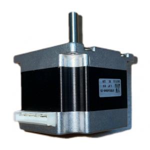
KG-5645 dc step motor two phase step motor cheap step motor Automatic assembly line
Description
Support power/voltage/revolution customization
Widely used in fans/juicers/coffee makers/unmanned aerial vehicles/range hoods/hair
dryers/smart toilets/exhaust fans/sweepers/industrial fans/electric shutter doors/electric wheelchairs.
/shredder/drill/eggbeater/mower/humidifier, etc.
Basic parameters
| Voltage(V): | 24V | Torque(Nm): | 1.5Nm |
| Input power(W): | 30W | Current(A): | 1A |
Outline Drawing

Stepper Motor Control We have seen previously that the motor coils need to be energized, in a specific sequence, to generate the magnetic field with which the rotor is going to align. Several devices are used to supply the necessary voltage to the coils, and thus allow the motor to function properly. Starting from the devices that are closer to the motor we have: A transistor bridge is the device physically controlling the electrical connection of the motor coils. Transistors can be seen as electrically controlled interrupters, which, when closed allow the connection of a coil to the electrical supply and thus the flow of current in the coil.
One transistor bridge is needed for each motor phase. A predriver is a device that controls the activation of the transistors, providing the required voltage and current, it is in turn controlled by an MCU. An MCU is a microcontroller unit, which is usually programmed by the motor user and generates specific signals for the pre-driver to obtain the desired motor behavior. Figure 7 shows a simple representation of a stepper motor control scheme. The pre-driver and the transistor bridge may be contained in a single device, called a driver. Figure 7: Motor Control Basic Scheme Stepper Motor Driver Types There are different stepper motor drivers available on the market, which showcase different features for specific applications.